AquaComputer launched a new flow sensor at the start of 2012 and caused quite a stir within the very stagnant world of flow sensors. Traditional flow sensors used in PCs fell in two categories. The first were the “spinny” type: small housings containing an impeller. The impeller is rotated by the flow and the speed of rotation was measured and usually communicated to the PC via a tach wire to a fan header on a motherboard. The second method was the use of a rotameter such as the King Instruments series which relies on the coolant flow to battle gravity and raise a weighted float. The float lived in a vertical tube of increasing diameter and the height of the float indicated the flow rate. Rotameters are rarely used these days except by tester’s as they are quite accurate when large enough. Both however have their issues. The impeller type were inaccurate and prone to breaking and blocking flow. The rotameter type were costly and large. AquaComputer previously had an impeller type design but decided to go with something different this time:
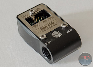
The MPS flow sensor doesn’t use an impeller, instead it takes a differential pressure measurement in a similar way to the way pitot tubes work. This means that there is nothing to slow down flow like a rotameter would, and there’s nothing to block flow like a broken impeller would. It also means it’s small:
The 400 in the name refers to the maximum flow rate range in litres per hour. There are other MPS sensors with different ranges but the 400 is best suited for most PC water cooling systems. The flow sensor comes with a USB cable and an optional “alarm” cable that can be plugged into a 3 pin fan header or it can be used to drive an indicator LED. Note that when it is plugged into a fan header that a constant RPM is shown and that it does not vary with flow rate (except when the flow stops). The USB cable connects to a motherboard USB header (make sure to plug it in the right way round). The flow sensor can also be connected to an Aquaero controller unit via the AquaBus connector (cable not supplied, although the 3 pin can be used in conjunction with the USB for the same effect) and it can also measure a standard 2 pin temperature sensor (not supplied). In addition the flow sensor also includes an internal temperature sensor. Here we see the sensor in use with the USB cable, alarm cable and external temperature sensor all plugged in to the unit:
One thing to point out is that the sensor outputs “raw” data from a pressure sensor that gets converted by a segmented calibration algorithm into a flow rate. Pre made calibration tables are supplied for 6mm ID tube, 8mm ID tube and 10mm ID tube. This means that if you want to use fatter tube like 7/16″ or 1/2″ or indeed anything that isn’t 6,8 or 10mm then you will have to calibrate the sensor yourself.
Because the sensor can measure pressure it can also be used as a fill level sensor in a reservoir, or simply as a differential pressure sensor to measure a specific component’s pressure drop (or gain in the case of a pump). This can be useful for verifying that individual parts are working as they should be and is cheaper than a professional manometer.
MPS 400 Internals
The MPS400 flow sensor is so small that it simply can’t house a lot of stuff. Therefore it was expected that it would contain some sensor that would integrate with a microcontroller and presumably that microcontroller would handle the USB and aquabus links and any ADC functions for the flow sensor and the temperature sensors. Taking off the front plate then we were not too surprised:
Connectors and the mystery sensor hidden under a sticker. Once the sticker was removed then the sensor could be seen better:
It’s a freescale part and you can see the datasheet here. You can just make out the two tiny barbs that push into the plastic housing that have a rubber seal around them. The nice thing is that the sensor is internally temperature compensated already. It is also supposed to give a linear output of pressure. Pressure of course is relative to velocity squared so the curve outputted by the DAC does indeed look like a square root function. Presumably the microcontroller is on the back of the PCB. I didn’t check because it’s of little interest.
So the MPS promises a lot and comes in a very small package but how does it perform?
Flow Rate Measurement Performance
In order to use the sensor we first have to install aquasuite. I quickly found the 2013 version on the AquaComputer website. It’s fast and easy to install and when it opened up you see tabs on the left side to select what you want to see. I first configured AquaSuite to use imperial gallons per minute, because that’s what my King Rotameter uses. The default setting only shows flow to the nearest 0.1GPM, you can change this later though for more accuracy. If we then go to the MPS sensor settings tab we see the following:
There are is a zero flow calibration button – useful if there is residual pressure across the sensor (perhaps because of a different orientation). The calibration file for the tubing size can also be selected as well as the degree of “filtering” the data received. The less filtering the more jumpy or “noisy” the readings are. To sweep flow I varied power and pulse width to a MCP35x2 dual pump. This gave me a wide degree of control of flow rate. I plotted the “raw” uncalibrated data vs flow rate as measured by my King Instruments Rotameter. The rotameter has a worst case accuracy of +/- 0.07GPM across the range:
Here we can see that the raw values cap at about 750. The exact maximum value depends on your zero-flow calibration result. I measured a few different ways because I was confused as to why the filtered results looked so much lower than the “fast” results. Plotting the maximum and minimum of the observed “fast” results showed that the filtering seemed to be nearer the minimum rather than the average result. Given how the filtered result still jumps around sporadically I believe that the filtering controls how long the last minimum observed value is displayed for. This is less good for accuracy but is more useful for a quicker response to a pump failure. If we also plot the range of observed minimum and maximum flow rate data at each pump setting we can see that the range seems to increase as the data value increases:
This implies that the error is a fixed percentage. As the full scale range is about 750 we can draw the conclusion that the noise is about +/-0.03%. This is similar to a medium size rotameter which is pretty good! If we then take our data (in this case the average of the minimum and maximum observed values), we can then come up with our own calibration algorithm to see how good the supplied algorithm is:
Here I used an over the top 5th order polynomial calibration to give a nice smooth curve even though a square root curve might be supposed to fit more accurately. We can then plot this alongside the measured flow and the results given by the supplied calibration file:
The 5th order poly cal shows extremely good results. However the supplied calibration is quite far off and also artificially limits the range of the sensor to 1.5GPM as this is the extent of the calibration file. Note that AquaSuite was rounding the data to 0.1GPM, changing the settings would improve the plot slightly, but wouldn’t account for the large 0.2+GPM offset over most of the range. This is easy to see when we plot the error of each calibration routine vs the measured data:
Here we can see just how good the sensor could be with a good calibration. It also shows how poor the supplied calibration was for this particular sensor.
Temperature Sensor
The MPS 400 also includes an internal temperature sensor for the coolant, as well as supporting an external temperature sensor. I connected an Aquacomputer coolant sensor to the external header. I then measured both sensors relative to my reference Dallas DS18B20 “one-wire” sensor located in a home made housing. I tested a wide range of coolant temperature by letting the system self heat slowly by unpowering the radiator fans while the PC sat idle:
The external AquaComputer probe tracked my reference probe very well. However the internal sensor was not only slow but had a significant ~2.5C difference in temperature even when finally settled:
It can also be seen in these plots that there is some curious behaviour around 30C. The external probe jumps 1C suddenly while the internal probe jumps 0.6C. As I hadn’t figured out how to get AquaSuite to log data automatically for me yet, I had been taking data manually and wondered if I’d simply made a mistake somehow so I ran the experiment again and this time logged it:
It happens on both the rising and falling:
While many people don’t intend to have their coolant go over 30C, it’s worrying that there is such a spike which again could be contributed to a poor calibration. AquaComputer have since found the bug in AquaSuite that was causing this and will be fixing it in the next release!
Finally if we plot the temperature step from data point to data point we can get a feel for how responsive and how noisy the sensors are:
If anything the AquaComputer external sensor is just as noisy and even a little more responsive than my reference probe.
Usage Scenarios
The MPS 400 was never designed to replace an accurate flow meter and it was really designed for two types of people. The first just want to know whether their flow has changed significantly. They are worried about a pump dying or a leak or a blockage. The second group of people are interested in their performance. Is their flow too low or too high. They are concerned whether they need to buy a different (or second) pump or whether they can turn the pump down and decrease noise. The usual metric for good performance is to be above 1GPM, larger gains are made before this flow rate and small gains afterwards. In this sensor we’ve seen that it can easily be 0.2-0.3 GPM off across this critical range. This means that for these users a personal calibration is useful because the provided calibration may not be good enough to prevent them buying an unnecessary pump. However as we’ve seen the flow sensor is actually much better than the supplied calibration let’s it be. For someone with the means to calibrate the sensor for their setup and average the data then very good accuracy can be achieved and this means that for someone like myself it can be used for more than the original intent.
Summary
Overall this device packs a bunch of features into a tiny package. The flow rate sensor is actually very good and much better than expected but it’s let down by poor matching to the calibration table. For some users it will serve the needs of a high-flow low failure risk meter that is good for coarse estimates. For those looking for accuracy you will need to calibrate it after which it can be very accurate. The internal temperature sensor is also best ignored. Given the price of $68 it might be assumed that if you’re willing to pay for the MPS400 you wouldn’t mind spending another $10 for a temperature probe.]






[…] sensors will be compatible – only the pulse style that is most common. Not the fancy new AquaComputer […]
How would you recommend calibrating this sensor suite (flow, temps) in a system? Any specific tool? Should it be re-calibrated once in a while?
I just found out that my multimeter has a type k thermal probe (no idea what that means, though). Is that enough to calibrate the internal thermal sensor of the mps?
Hah well thermal probes themselves often need to be calibrated. Since that review was written AquaComputer fixed the bug with the non linearity, so it should be a lot better now. Unless you’re really testing stuff it’s probably good enough to be honest. If it’s not it’s probably easier to buy a 10$ probe and add it in the loop instead.
Comments are closed.