


Pump Restriction / Flow Testing
Essentially these tests measure the flow rate and pressure output of the pump. By comparing the results of the same pump fitted to different tops we can make an assessment of the top’s performance by comparing it’s results to others.
To test pumps we use a flow meter and a differential manometer and vary restriction by adjusting a brass gate valve. We adjust the gate valve to give different flow points and measure the pressure “gain” across the pump using the differential manometer. To better understand how to read these plots check out this guide.
This is the first Reservoir/Pump Top combo I have tested, and from the outset I was apprehensive about the ability to get accurate results. The main reason being that on stand alone pump tops the Low Pressure side take off is fitted directly to the inlet port. On res/pump combos such as we are testing here, the pressure take off can only be fitted to a port on the reservoir. For this reason I was never certain how accurate or meaningful the resulting data would be, however we went ahead anyways determined to get some sort of meaningful comparison.
As with all my Pump Top testing, a trusty Aqua Computer D5 USB is utilized. It’s an electronically controlled D5 Vario which easily connects to a laptop via USB. This allows precise control over the pump operating speed and provides the pump RPM when in operation.
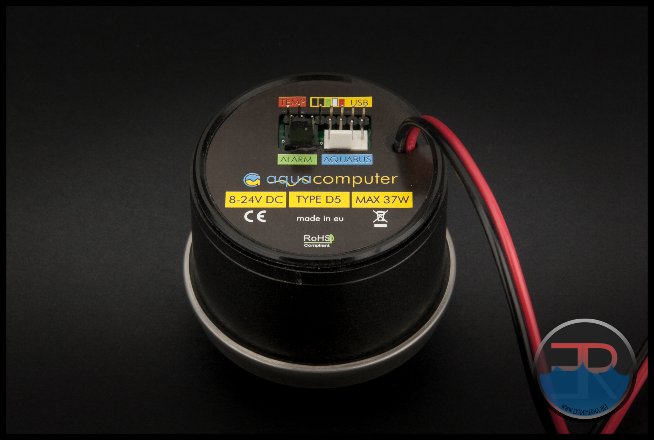
Using Aqua Computer’s Aquasuite software, the D5 USB can be controlled from a minimum power of 25% to a maximum of 100%. Keeping in line with recent testing, power levels for the MMRS-TRP’s testing was 40%, 60%, 80% and 100%.
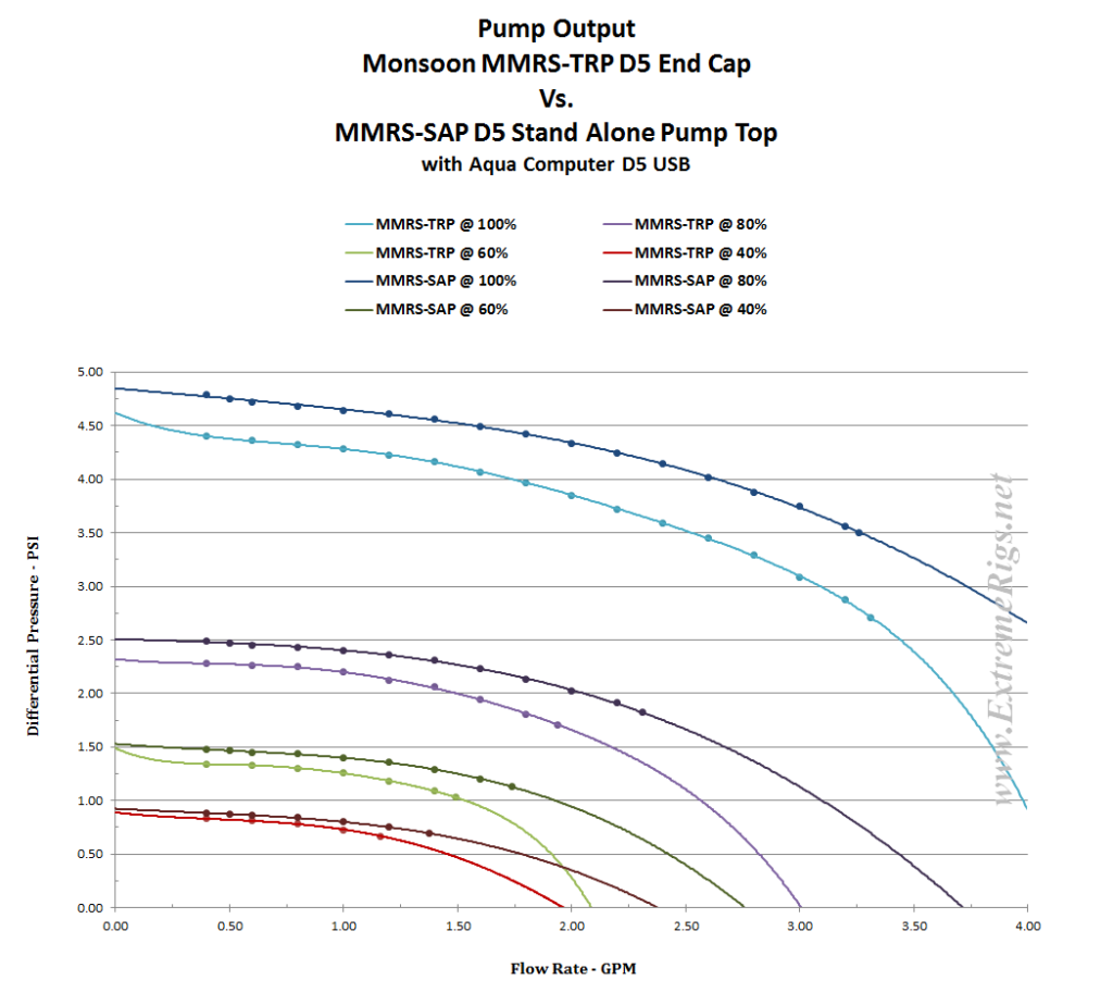
After logging and processing the data, it became apparent that my initial concerns for obtaining “accurate and meaning data” were justified. The TRP volute is virtually identical in design to the SAP, so we had a good idea of what the TRP’s performance should be, but the data was just not close enough to be considered usable. It’s not that the data taken during logging isn’t accurate, more so that something was effecting the readings being taken. The prime suspect was the PSI take-off for the low pressure side – inlet for the pump top.
I’ve decided to include a plot derived form the data of that first logging run to give you an idea of the difference that the PSI take-off placement made. Keep in mind that the 2 pump tops are “virtually” identical. For testing the SAP, the inlet pressure was able to be taken directly on the inlet port, while the TRP required the take-off pressure line at the top of reservoir (the same MMRS 150mm res we used in the step by step assembly)
We knew that our TRP data could not be used as a direct comparison to anything else, but we felt it should have been much more in-line with the SAP’s data than it was. During the resulting brainstorming session numerous reasons for the difference were debated.
- O’ring size – this may affect the output pressure because the pump is not sitting as low into the volute as it’s designed to be. However it was the same for both tops so this is unlikely to be the cause.
- Indents from injection mold pins causing turbulence in the TRP volute causing weaker output – while this is possible it seems unlikely to effect performance as much as was recorded.
- Size of the inlet to the pump – SAP is the ID of a G 1/4 fitting thread while the TRP is the OD of a G 1/4 fitting thread – this difference is actually likely to make some sort of difference in the pump’s output but we had no way of testing or determining if this was the cause of the data variance.
- Placement of the inlet side PSI take-off – this is the most likely reason that we kept coming back to, but there was no way of changing the take-off position on the TRP. We could however add a reservoir to the SAP.
So it was decided top re-test the SAP with the same reservoir that was used with the TRP with the goal being to get similar results (if not the same) as the TRP’s data.
After re-testing the SAP with the same reservoir attached as was on the TRP during it’s testing, the results are much much closer than we saw in the first logging run for the TRP. While the TRP and SAP are almost identical internally, the slight difference of the inlet size to each remains and is most likely the contributing factor to the slight variation between the two sets of data in the following chart.
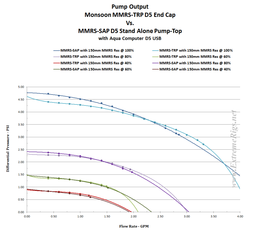 Satisfied that the TRP test results are similar enough to the SAP when tested with the same reservoir set up, we feel confident in saying that the TRP has very similar output to the SAP.
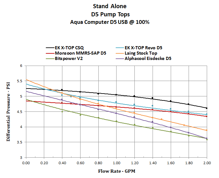
Therefore we believe the SAP’s data can be used to compare the TRP against other D5 pump tops we have tested. Below is a SAP comparison plot for 100% pump power which we have zoomed in on the usable range. More SAP data can be found in our SAP review.
 We certainly took the scenic route to get our TRP’s meaningful data, but we believe we got there in the end. We knew the TRP should have very similar output to the SAP, we just had to prove it to ourselves and have data to back it up.
Next up – Summary.


Great review! You mention a UK based re-seller has “committed to stocking the extensive MMRS inventory”… do you know who this is? I cannot find any UK company that has these products listed, only US based ones. Thanks.
We thought OCUK were going to be stocking them, but haven’t received confirmation. CaseKing (Germany) however have ordered them.
OCUK have contacted and said that they now have stock: https://www.overclockers.co.uk/water-cooling/components/reservoirs/modular-reservoirs
Very good review, i have just one question that i did not find anywhere, with this 150mm tube config, including pump cover, what is the total assembled length of this pump/res combo? im looking for a small pump/res combo for mini itx loop im planning, and am well aware of all the options out there, but this is just a sexy looking pump/res, was wondering how long it is with your review config so i can know how long it will be with the 50mm long tube *simply by deducting 100mm of course).
Rather than just give you the answer to you question, which is 202mm.
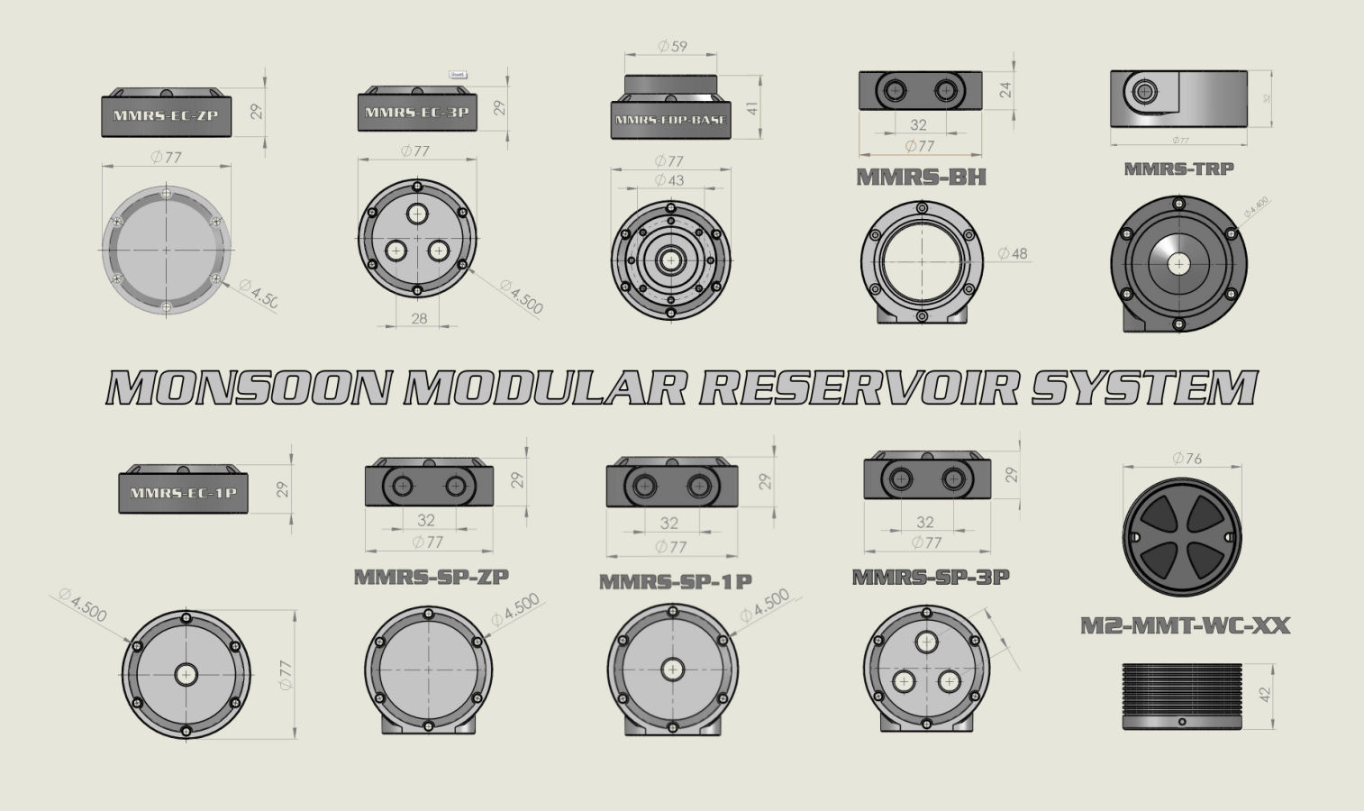
Let’s take a look at the MMRS size chart so you and others can confidently work out the MMRS reservoir lengths prior to placing an order.
Starting at the top of the assembly, an End Cap must be selected. These are all 29mm high. Remember to add you fitting or stop plug height if you select an end cap with top ports.
Next in line is the reservoir tube, in this case let’s make it 100mm.
Finally an End cap for the bottom must be selected. In this case we want the TRP (D5 pump mount) and the cover that must be mated with it, 32mm and 42mm respectively.
Now we simply add up the height of the chosen components to get the overall height.
29 + 100 + 32 + 42 = 203mm
Simple Right 🙂
The discrepancy with my answer and the sum total is that my EC-3P only measures 28mm, not the listed 29mm.
If you are adding a D5 pump stand, add another 12mm to the total.
Hope this helps.
f_f
wow man, kudos on awesome reply!
i am actually planning my first loop, and its in the NZXT Manta, imma plan to go all out with rigid tubing as well because… might as well.
Pump+Res has been my only thing, since im a silence freak and aim at D5 no matter what.
Case basement aint an option since my HUE+ occupies that space.
So far the Monsoon is the leading candidate also thanks to their mounting system.
Also, noticed they mentioned all the measurements in the article as well, but did not think of it when i read it xD
Again, amazing article, reviews like these are really helpful.
And of course thanks to fast_fate for great comment 🙂
On ppc shop is shown, that lightbulbs can be mounted even if using grasshoppers … yes, the bulbs are on others angles to the grasshopper, but still is possible to have both, grasshopper and lightbulbs
http://www.performance-pcs.com/monsoon-mmrs-fully-assembled-and-customizable-reservoir-style-2.html
only 1 thing i would appreciated: mirrored pump output (MMRS-TRP)
Just wondering but does anyone know how far apart the holes for the reservoir mounting brackets are?
Comments are closed.