


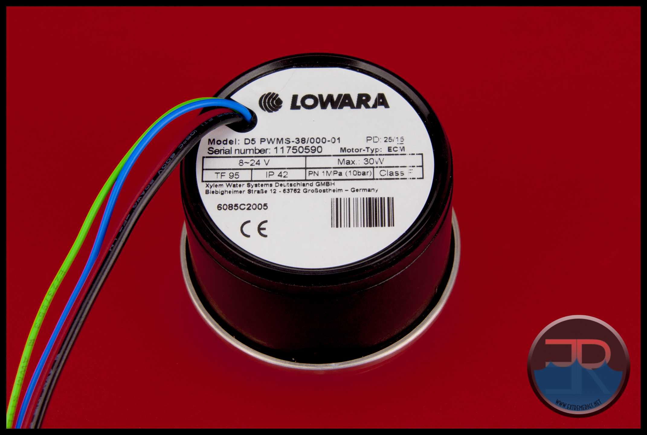
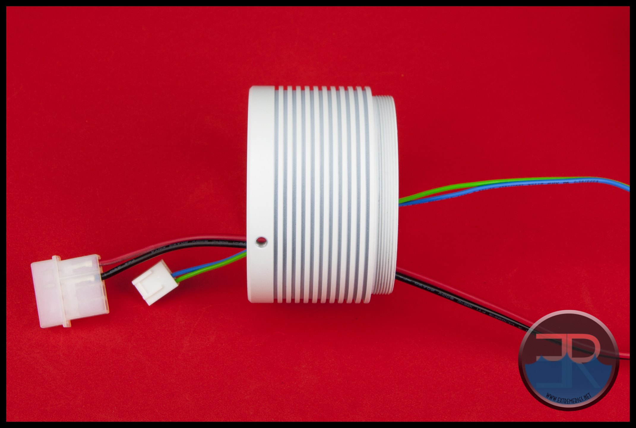
We’ve chosen to use EK’s PWM version of the D5 because it’s 4 wires will test out the wire pass through slots in the end cap of the MMRS-SAP. Hopefully they will all pass through.
Start off by grabbing the pump top and the supplied O-Ring seal. Ensure both parts are free from foreign material to ensure a good seal.
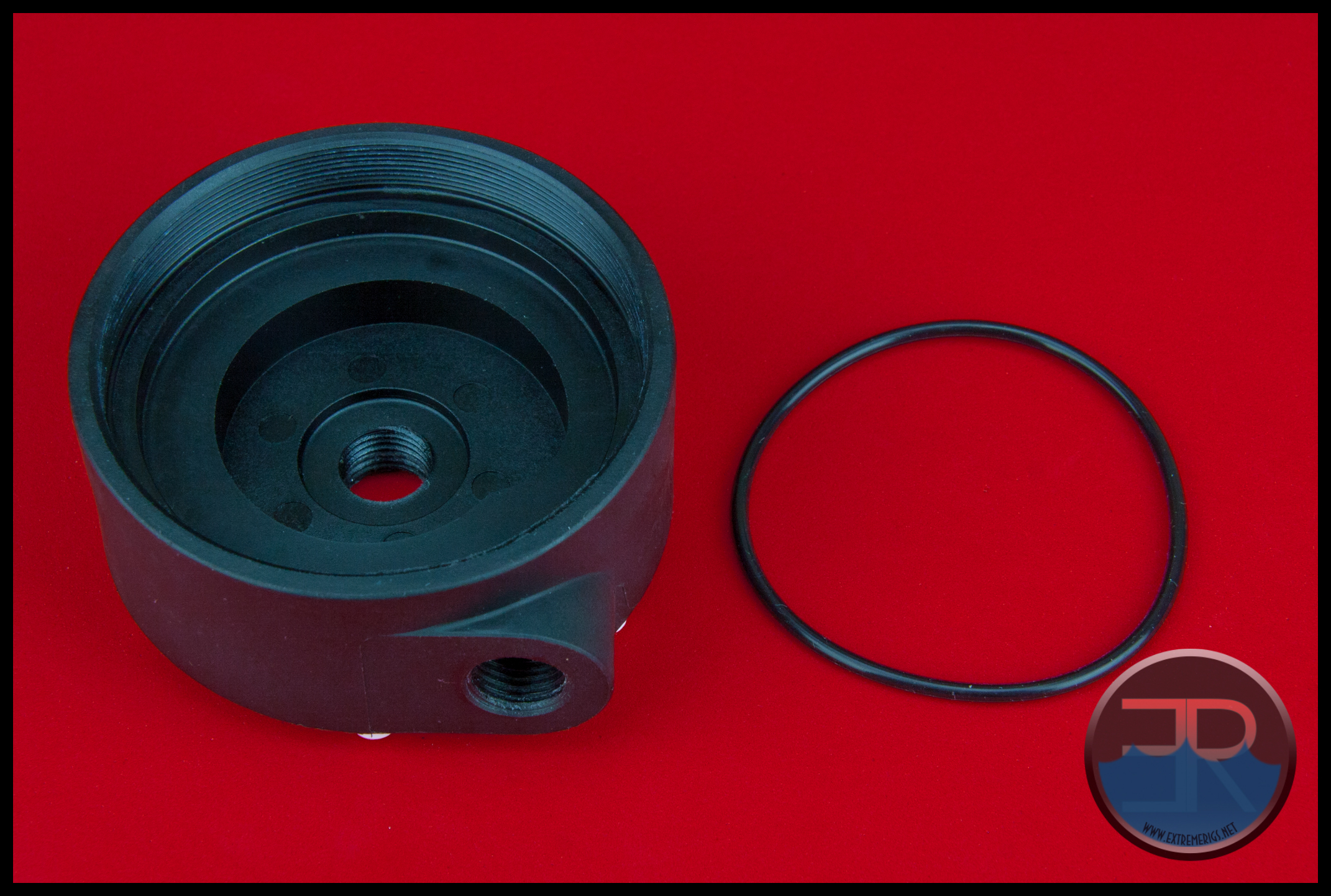
NOTE: Most users will know there are 2 methods that D5 pump top designs use for placement of the O-Ring seal. Either the seal goes into the pump top (as is the case with the MMRS design) OR the seal goes onto the shoulder of the actual pump. It would be handy for newbies and experienced users alike if Monsoon added a note with the O-Ring advising where the O-Ring should be placed when assembling the SAP with a pump.
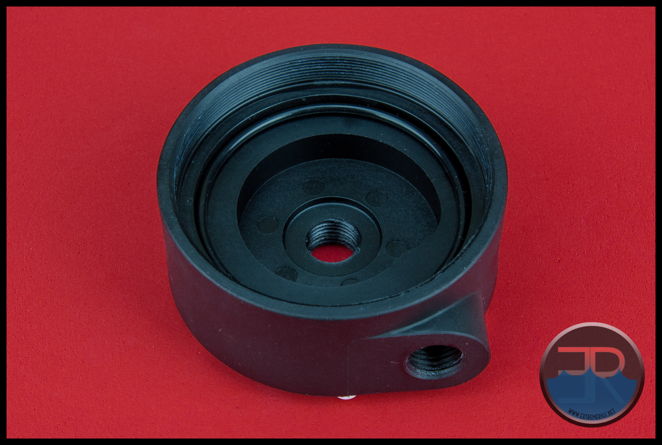
Place the seal into the pump top.
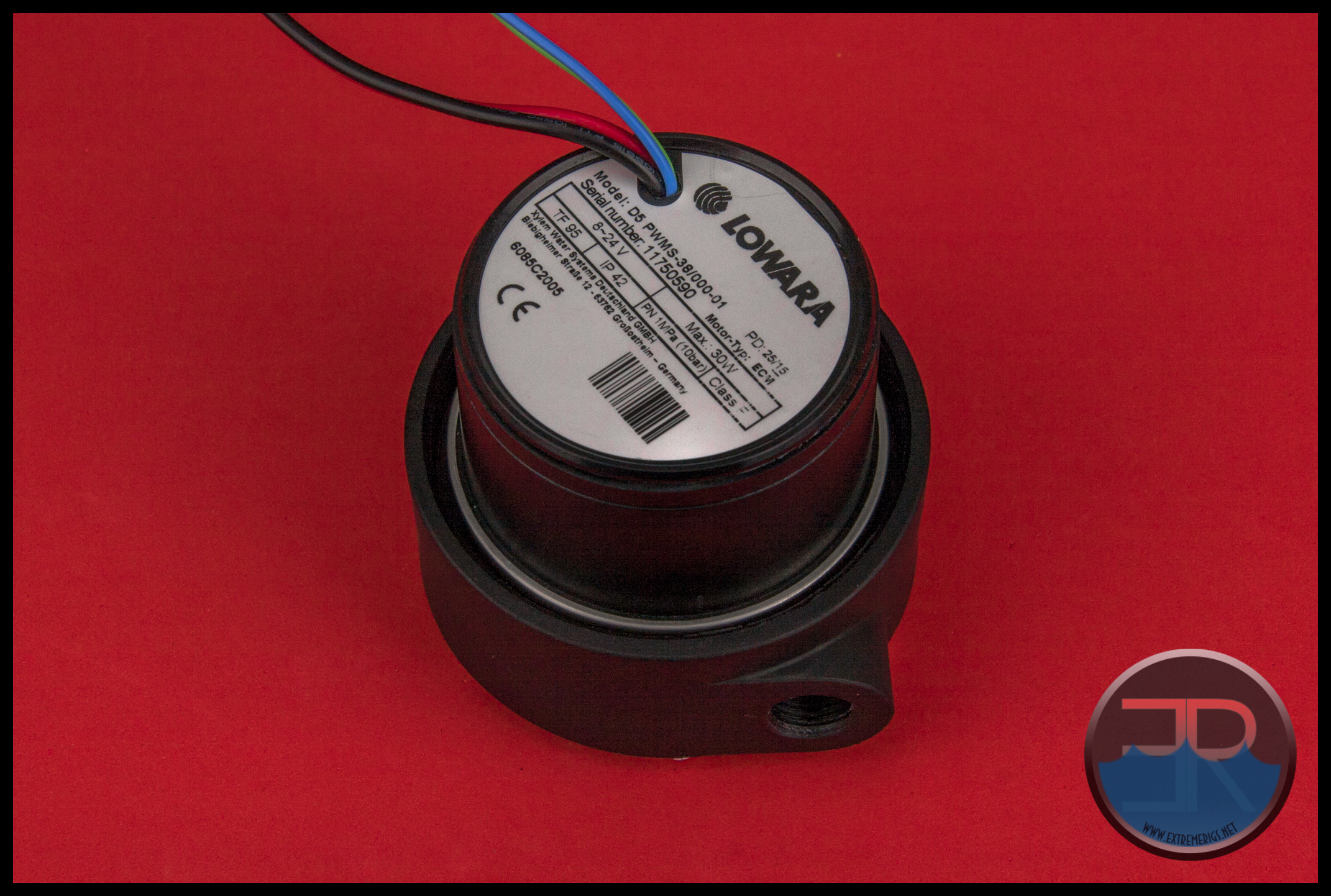
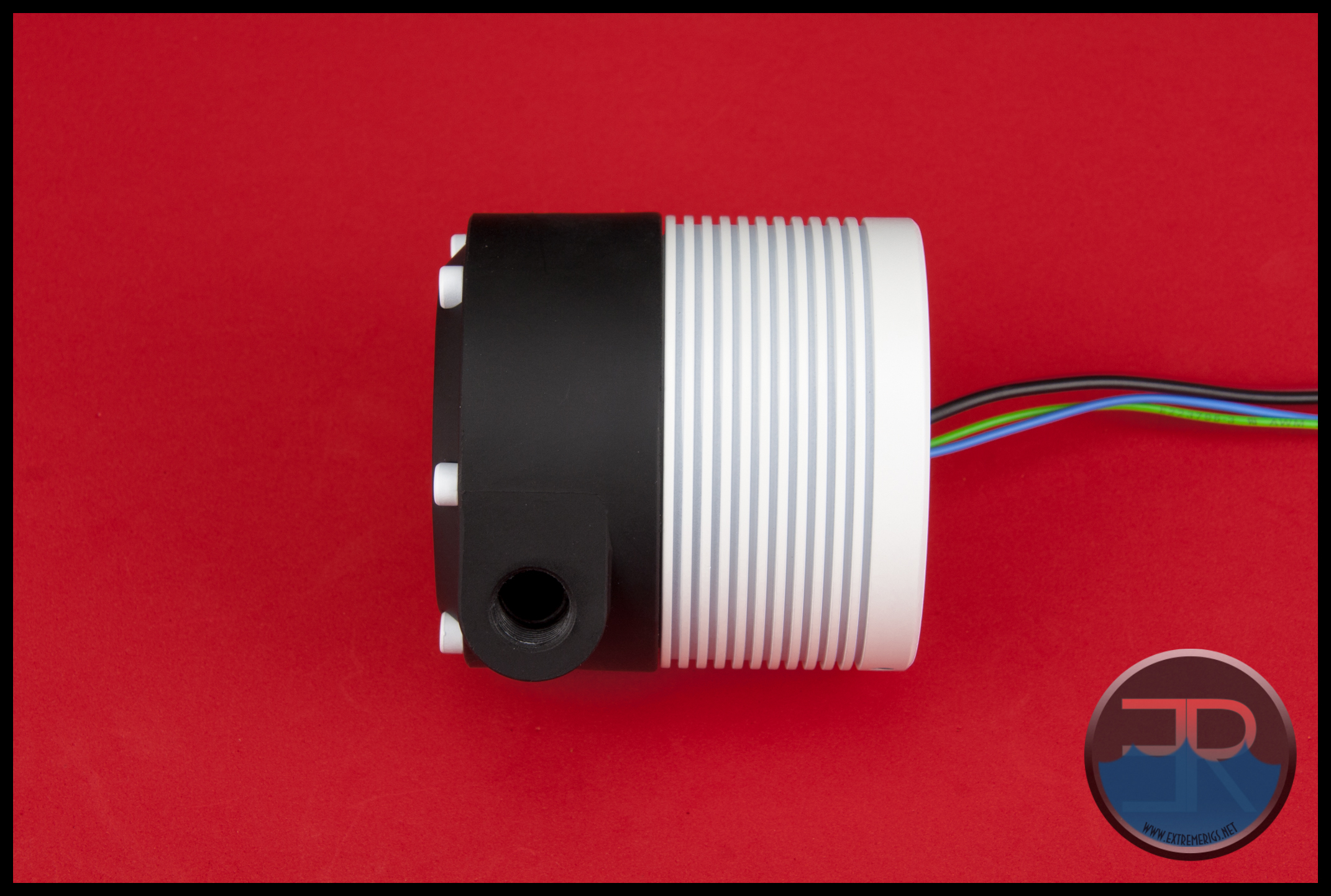
When the seal in position take the pump and place it into the MMRS top. The pump’s wires in most instances will probably be best placed opposite to the direction the outlet port is facing. This will vary depending on where the assembly is being mounted and which direction the wires need to go to be connected.
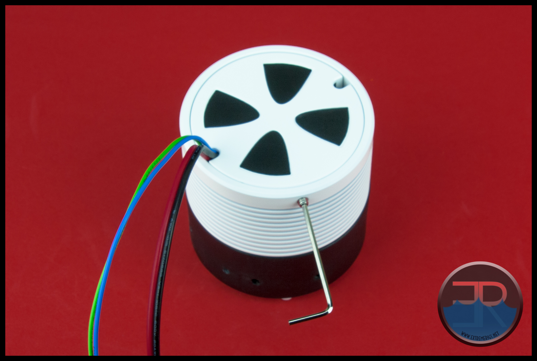
 Now take the wire connectors and pass them through the clamp/cover from the threaded side to the end cap side and slide the pump clamp/cover up to the top.
BEFORE you start trying to screw the two parts together, ensure the 2 pieces are parallel to each other and slowly turn the cover anti-clockwise until you feel and hear a click which indicates that the start of the thread on each piece is aligned to the other.
Now slowly and carefully turn the clamp/cover clockwise to get the threads started. Once started, continue screwing the end cap down until you fell some slight resistance which indicates the O-ring seal is starting to be compressed. At this stage I found it useful to push against the back of the pump to keep it from spinning (and throwing the wires out of whack) as I tightened the clamp/cover about another 1/4 to 1/3 turn until tight.
Even with some pressure against the pump, it still turned slightly during tightening, so you may want to consider having the pump wires offset a little before starting the tightening process.
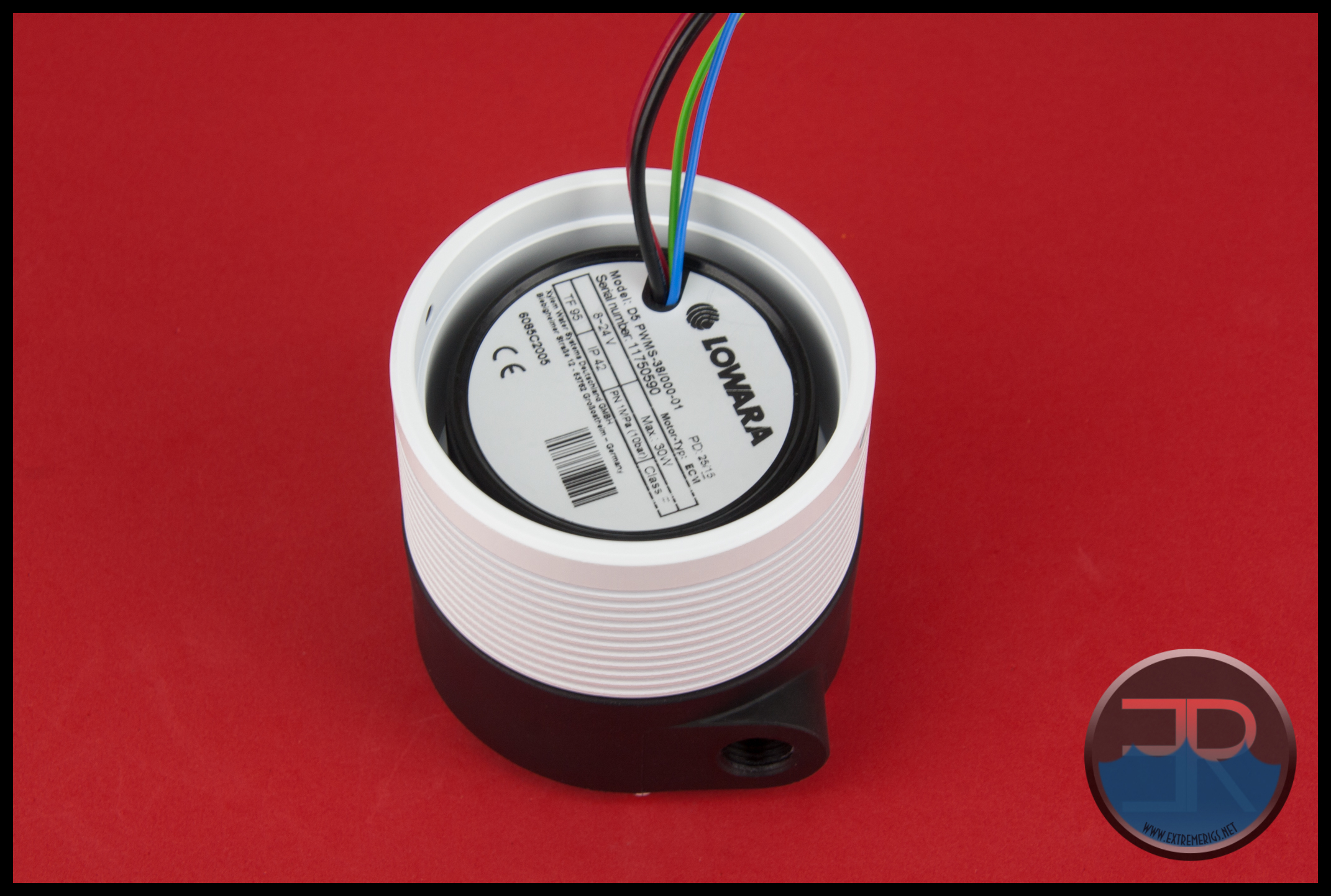 In the photo above you can see the lip that the end cap sits on is clearly above the end of the pump. It has to be higher to allow a little space for the wires. The reason I point that out is originally I thought the foam inside the end cap was for vibration dampening, but after seeing it makes no contact with the pump I assume it is for sound absorbing purposes only. How effective it is, well I have my doubts that it will do much at all.
With the pump locked in place next step is to put the end cap in place and tuck the wires into one of the wire cut-outs of the end cap.
The wires should be facing roughly in the direction you want them to exit already, so it’s a matter of simply giving them a little bend to suit, placing the end cap into position and nipping up the 2 small grub screws to secure the end cap.
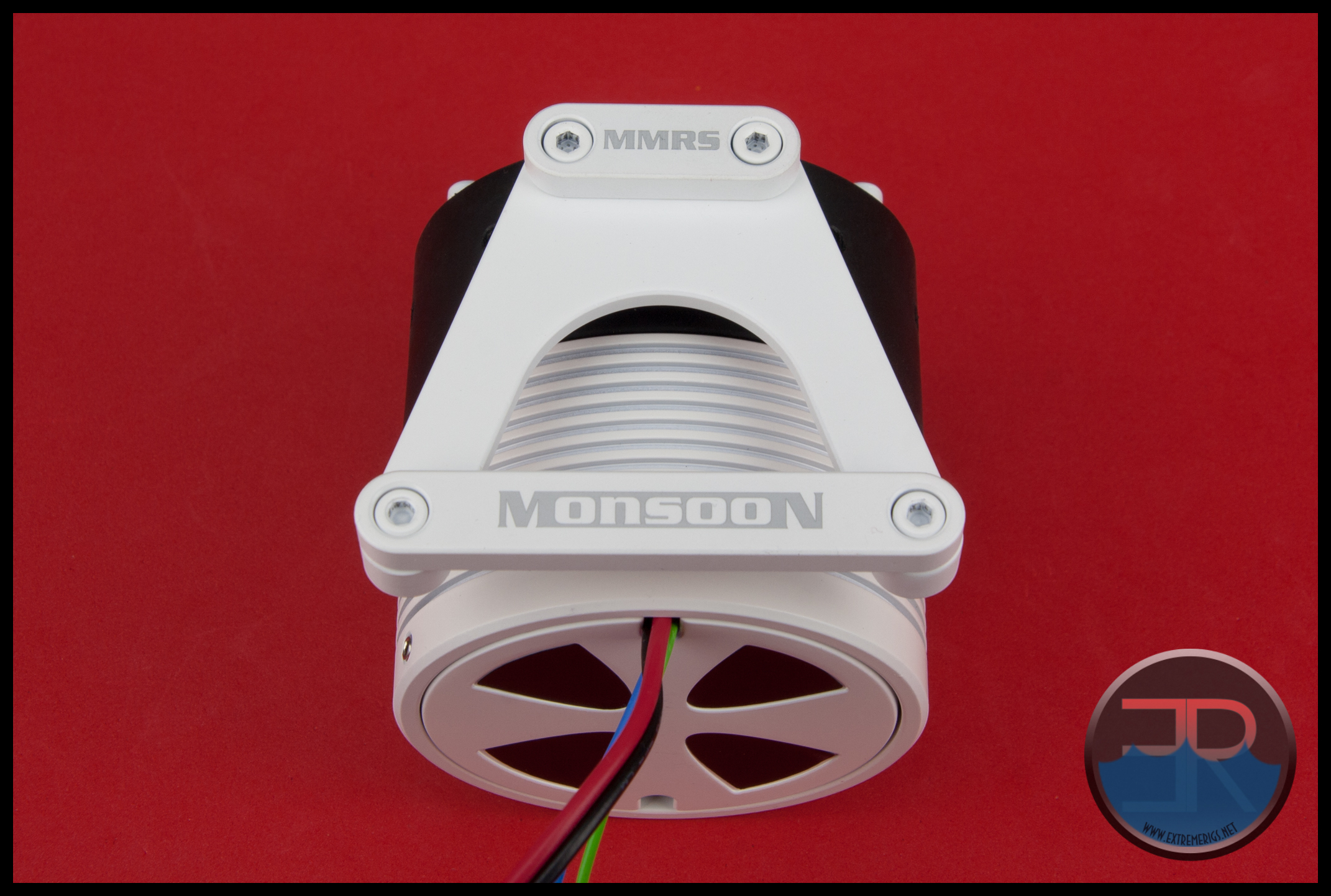
 As we can see, it’s a tight fit for the PWM D5’s 4 wires passing through the cut-out of the end cap. It will be even tighter with sleeved cables, if they fit at all.
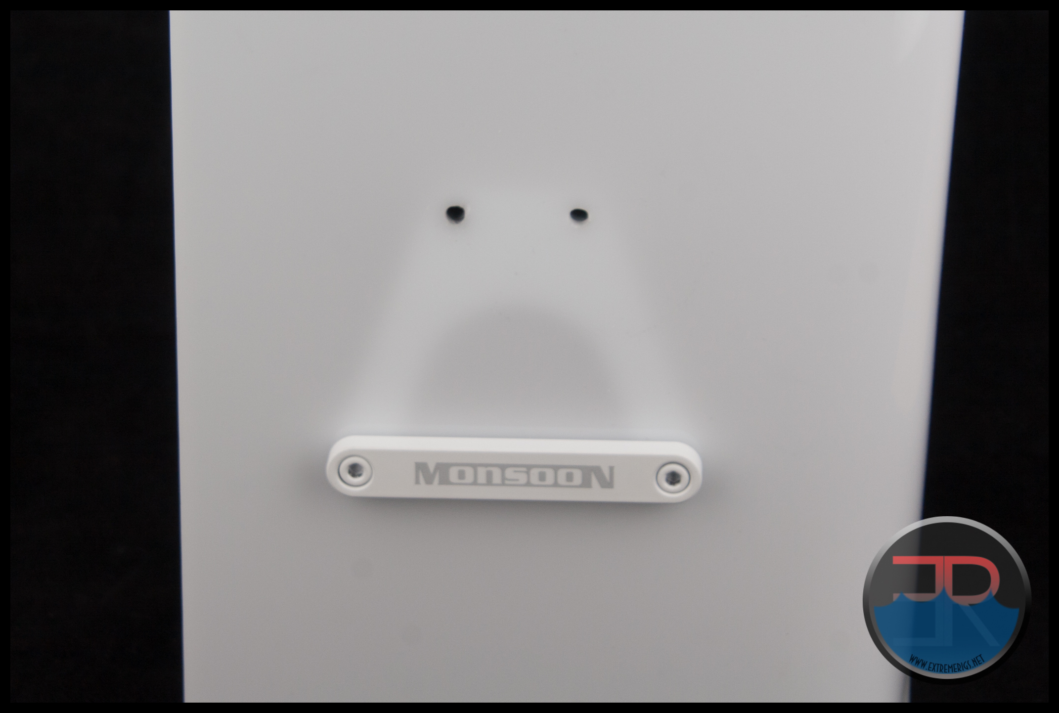
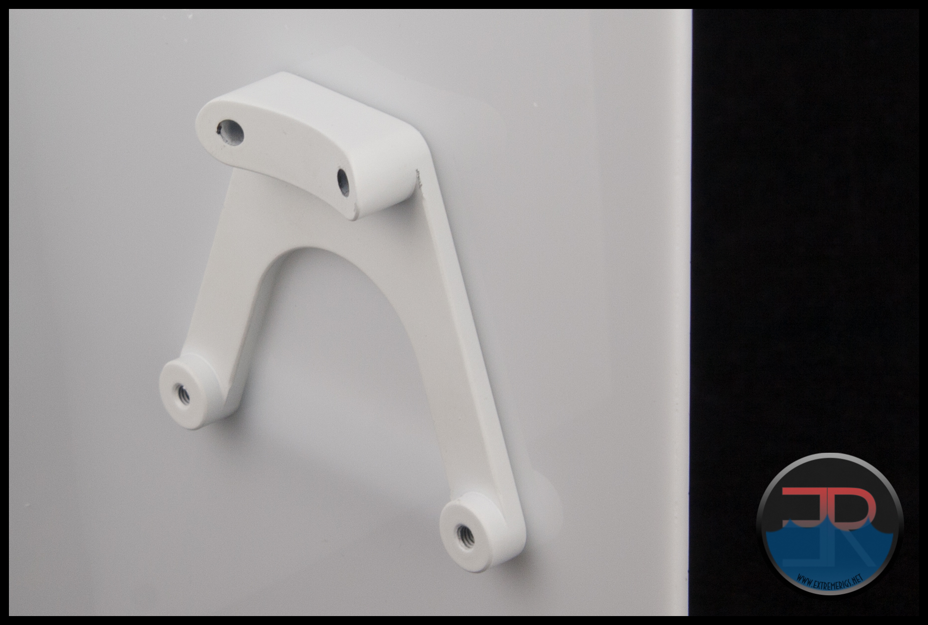
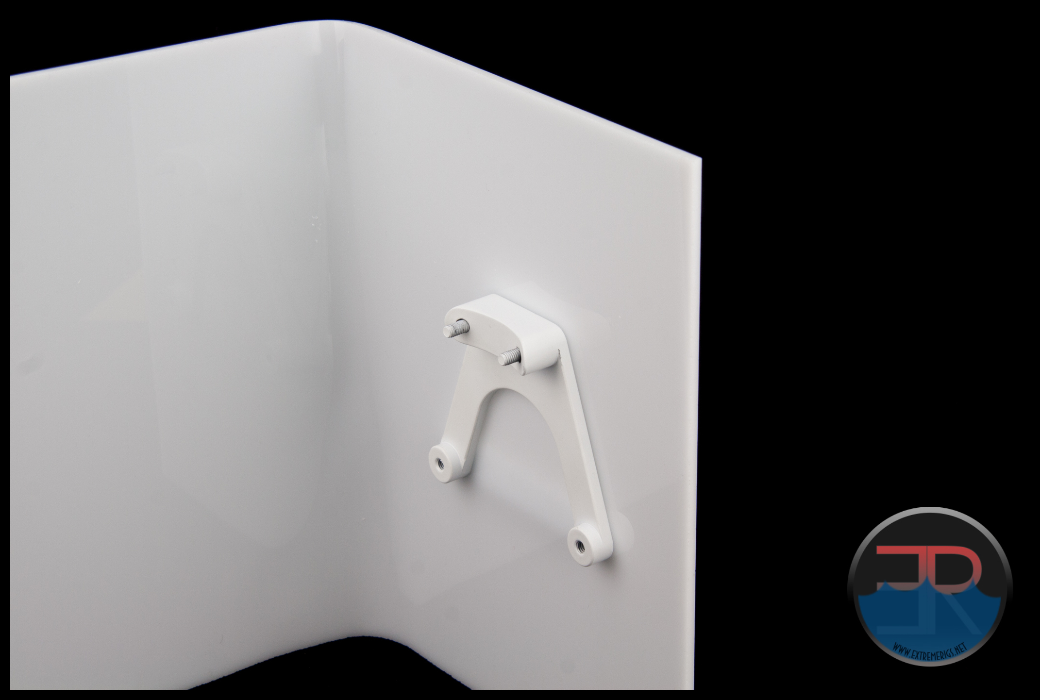
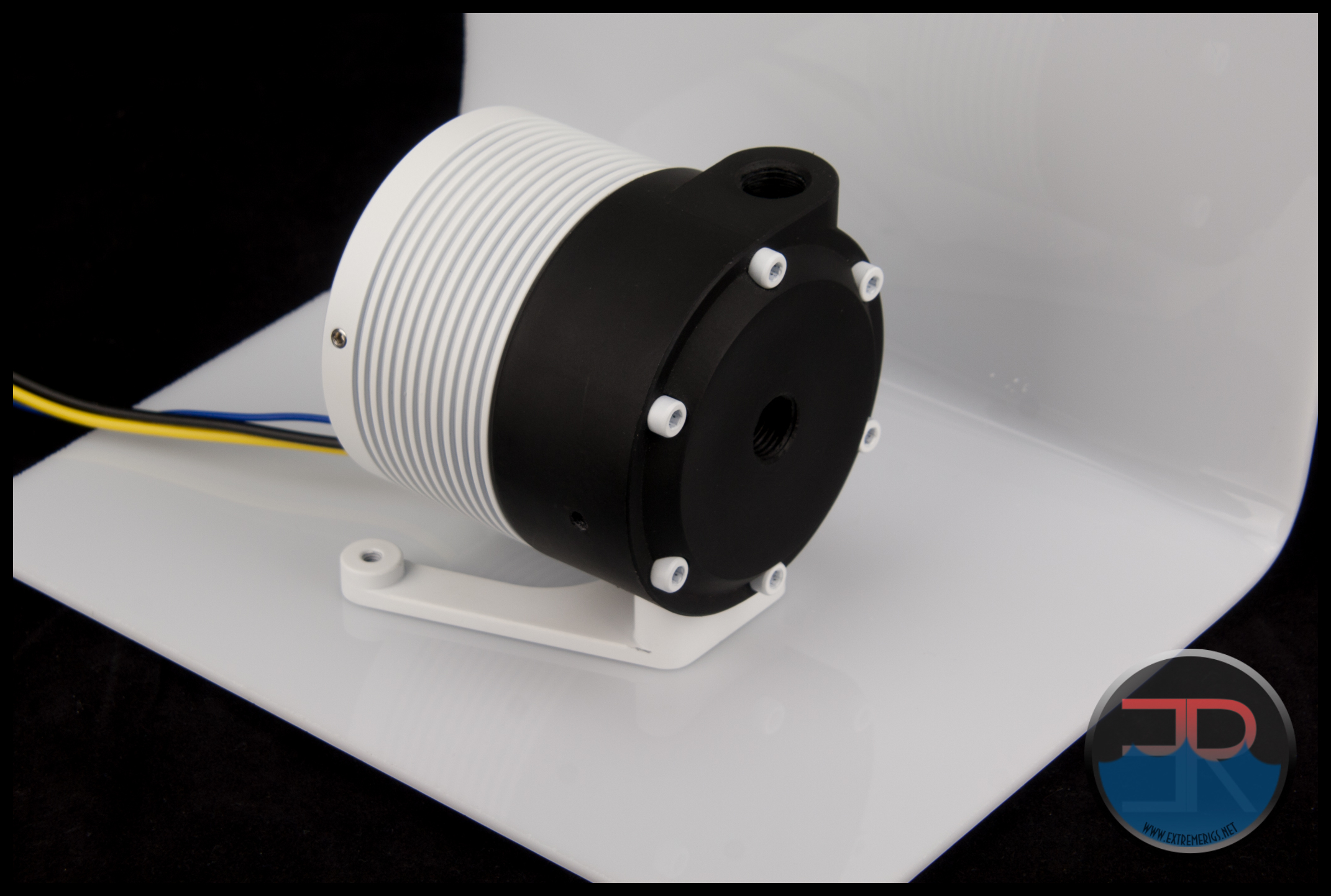
In this assembly we simply reinstalled the mounting bracket to the pump top by bolting the small end of the bracket to the pump top.
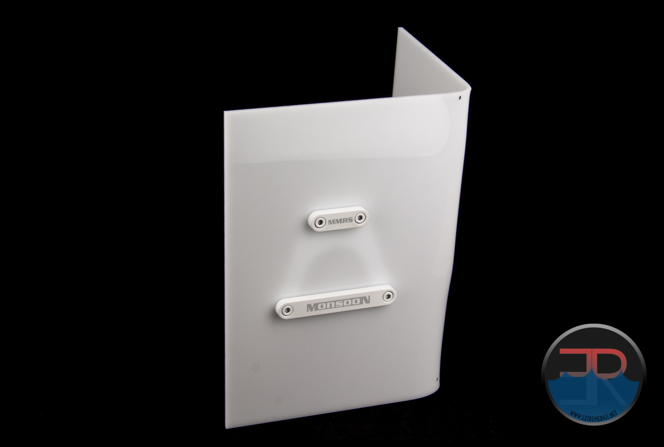
To show you a mock installation, a piece of acrylic was (very roughly) bent. We’ll use one face of this to simulate a chassis panel to which the SAP will be fitted to. The acrylic is 3mm thick and therefore represents even the thickest chassis panels on the market.
If you get your holes drilled perfectly as per the template, a 4mm drill bit is the perfect size to pass the 4 fixing bolts through.
The easiest way to mount the assembly is to have the pump fitted first with the end cap in place and with the wires already facing the direction you want.
Grab the 2 short bolts, the wide clamp bar and the mounting bracket.
Insert the bolts through the clamping bar and pass them through the chassis panel.
Get both of these bolts stated in the corresponding holes of the bracket and tighten, but don’t torque down just yet. at this stage we just want to hold the bracket in place until we get the short clamp bar and screws secured. If your holes were drilled spot on, there will be no movement anyway.
The short clamp bar screws should push easily through the holes in the chassis panel when putting the short clamp bar into place. If they do not push through easily (make sure bottom 2 are not tight), I would suggest using the next size drill bit to enlarge the holes in the panel slightly otherwise you could easily end up cross threading the holes in the nylon top.
The next part is probably the trickiest, although not difficult at all. It is essential that the bolts start mating correctly with the threaded holes in the pump top. In a real chassis you probably won’t be able to see much and you may have to “feel” your way through the process.
Pushing the top onto the curve of the bracket is essential to avoid cross threading, then gently push on the bolts to locate the hole to screw into.
This was my “practice” run through without a pump installed.
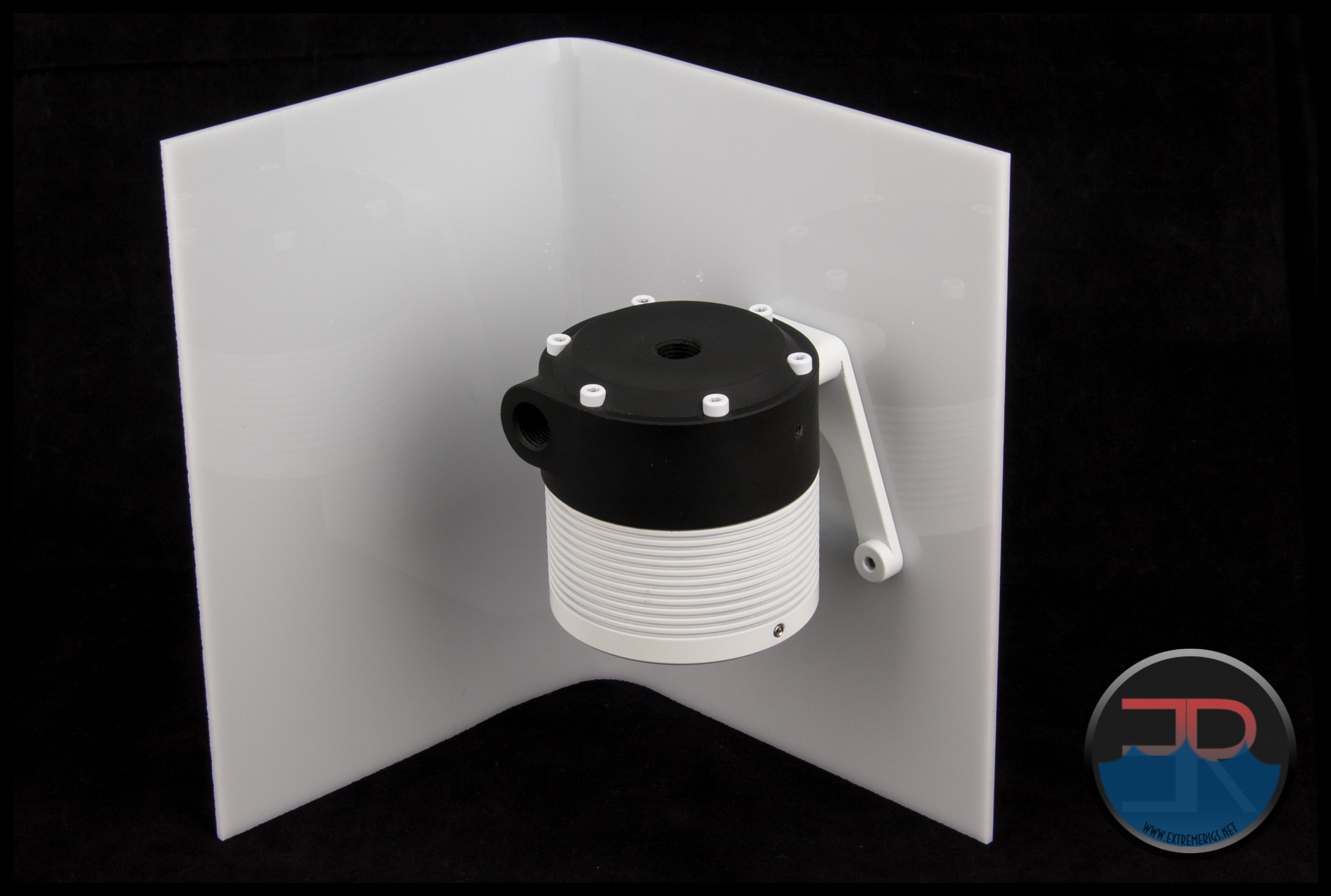 I say practice because I was going to make a hole and put a grommet in place for the pump wires (and sleeve the pump wires) but time got the better of me and I just fitted a stock D5 Vario instead.
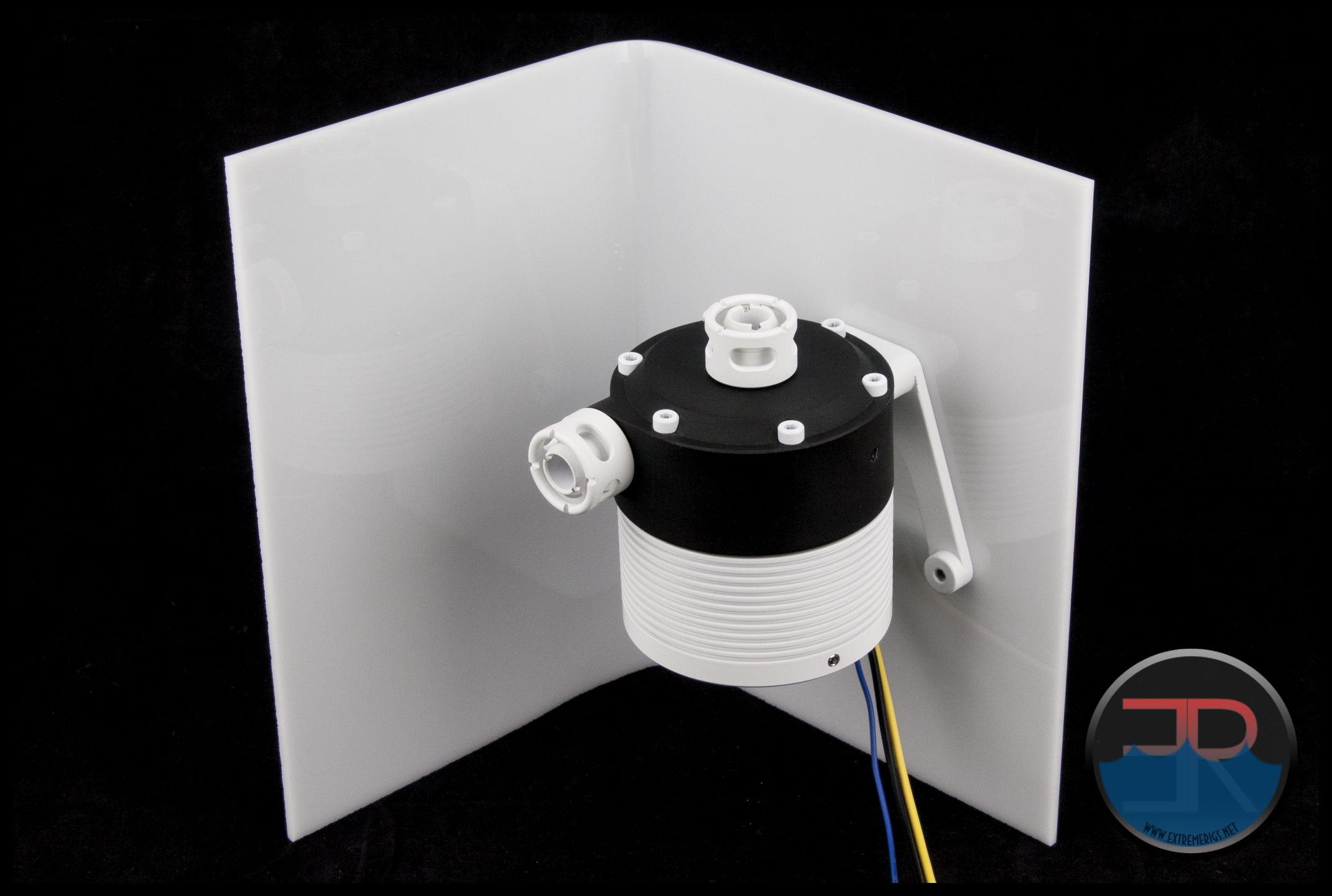
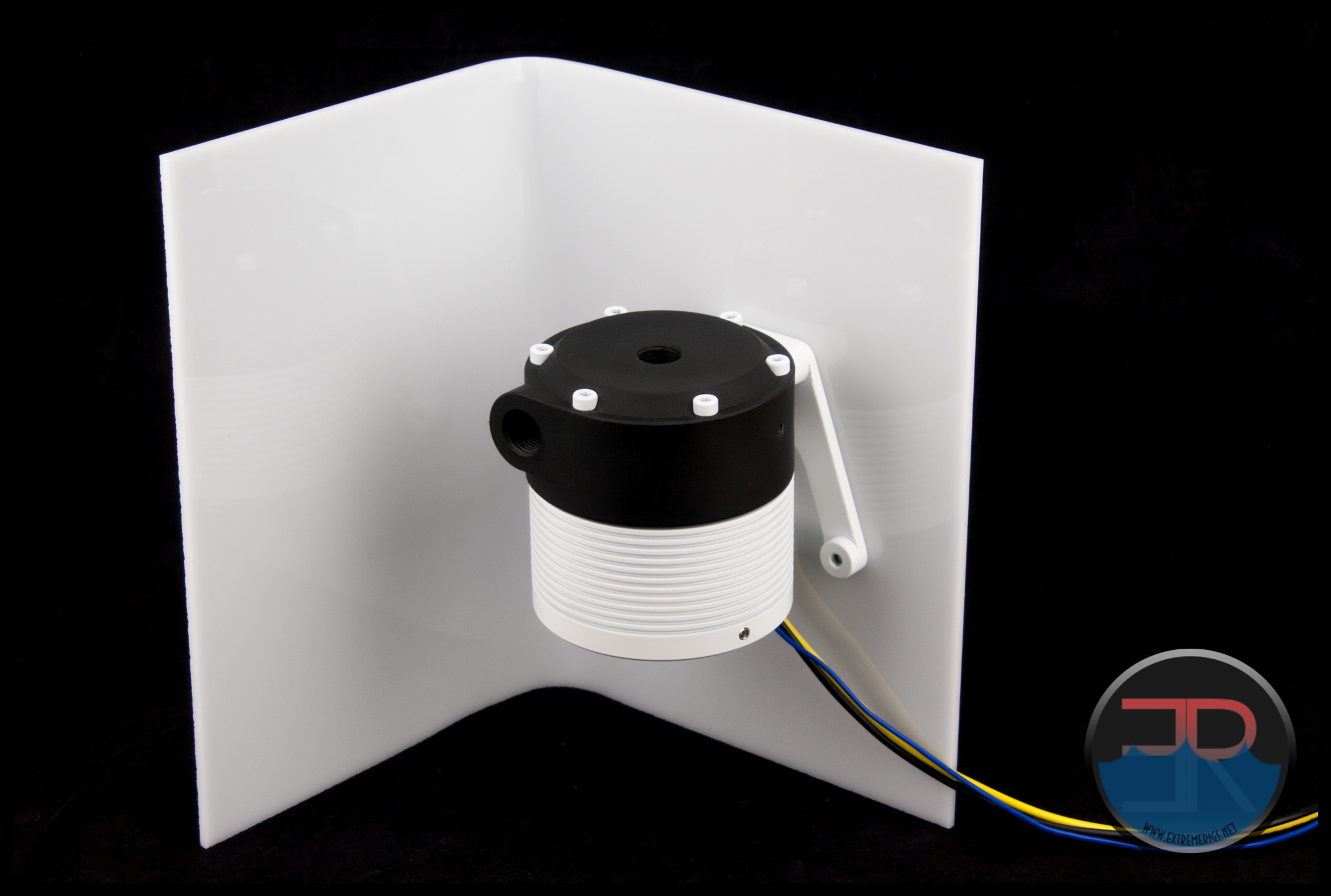 Here it is flipped to simulate being installed on the floor of the chassis:
To make up for not sleeving the pump (until later) and doing the cable pass-through, I screwed some fittings into the ports 🙂
Installation of the pump was straight forward then, with the keys points being that the seal goes into the pump top and to be cautious when mating the bolts (and fittings) into the nylon top.
Let’s now discuss compatibility with the different versions of the D5 pump.
We’ve seen that un-sleeved, stock wires for both the PWM and Vario with RPM variants of the D5 fit through the end cap cut out, therefore a basic D5 with only the 2 power wires will easily fit through, even when sleeved.
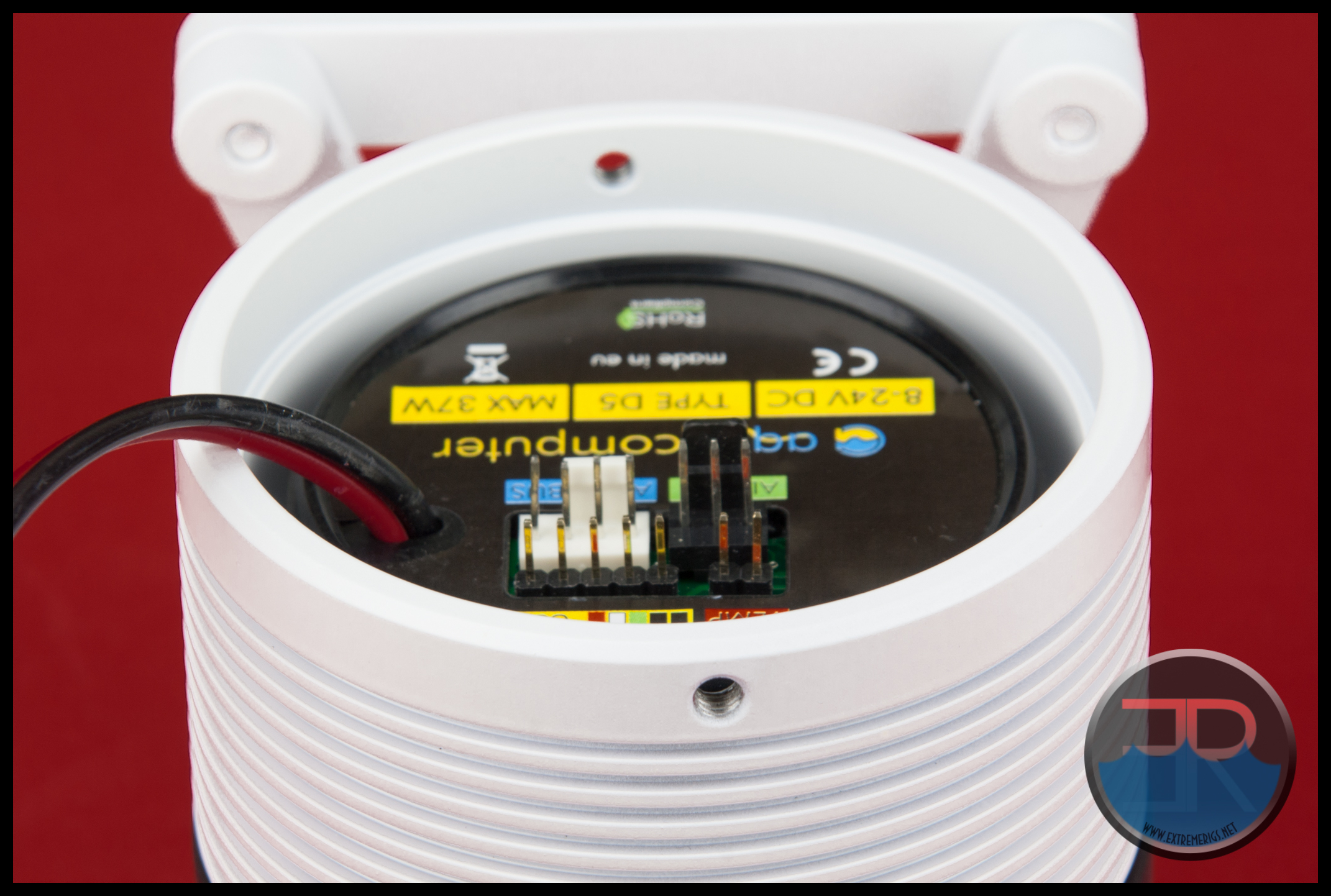
But there is another D5 variant, Aqua Computer’s D5 USB version.
Basically the end cap can not be used with this version of D5 due to the height and location of the headers on the pump. With the USB D5 you could try modding the end cap to suit or simply leave the end cap off the assembly.

 I have heard rumors that Monsoon are considering making an extended end cap to accommodate the USB D5, however I wouldn’t be holding my breath for it to come out before purchasing the SAP. It may be a pleasant surprise down the track if it was ever made and released.
The next couple of photos give a visual reference to size of the MMRS-SAP against the EK Revo top.
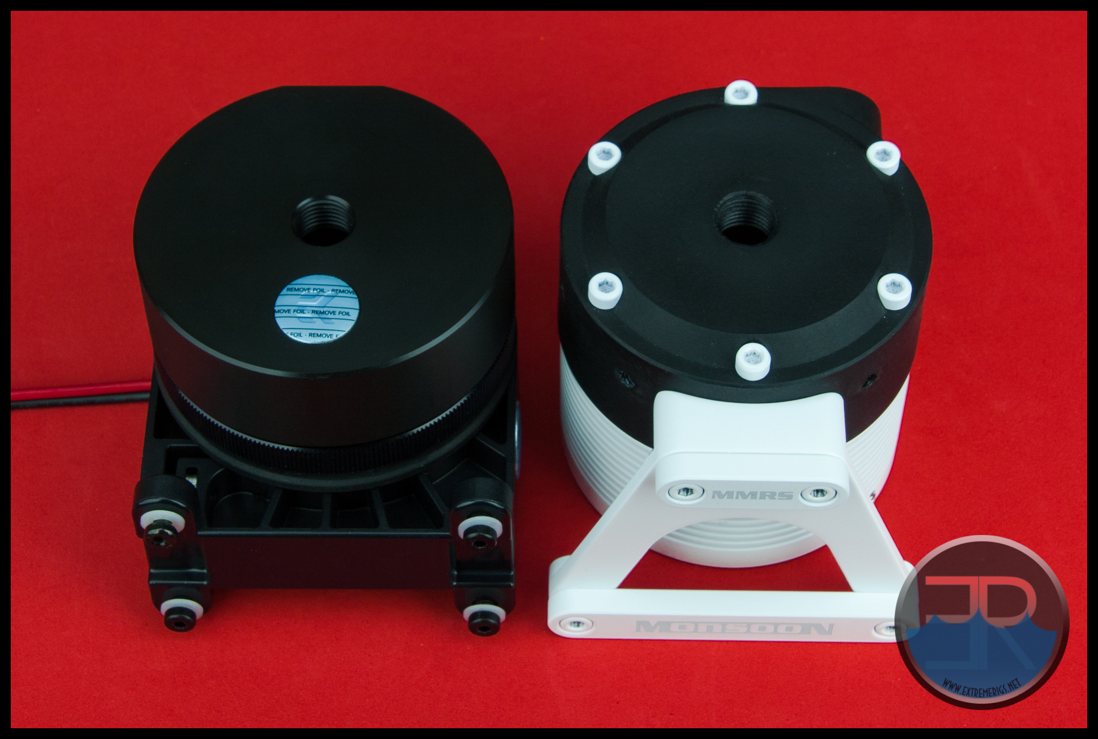 Both assemblies are pretty much the same in height, width and depth when including the brackets.
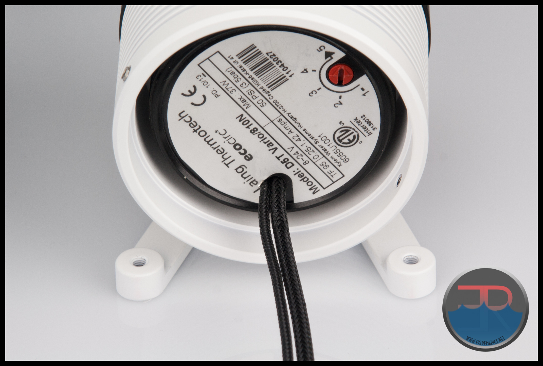
To fully assess the end cap and the cut out notches I just had to bite the bullet and sleeve a pump which I had been putting off until this review was nearly complete. I decided on a D5 Vario with Tach wire to sleeve as it is probably the most common D5 out there. With a Vario I could also show how a basic D5 without the tach wire would look and give an indication on whether or not the 4 wires of a PWM D5 would fit through.
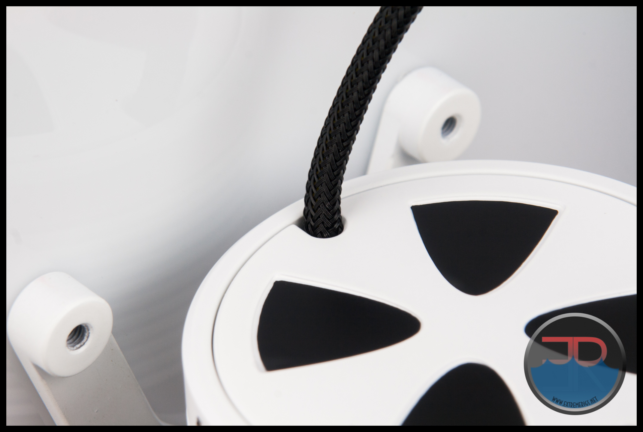
So first the standard D5 with no Tach wire, just the 2 power wires sleeved.
This is a perfect fit through the wire cut out in the end cap, snug but not tight with just a little room to move. This is perfect.
Next up is the Vario with the Power and Tach wires sleeved.
I was able to pass these through the cut out, but it was very tight and was more of a “squash them in” rather than place them in. So this is definitely doable, but the cut out design seems to not have this way of doing it in mind.
I did not sleeve the PWM D5 which has an addition wire that would normally go in the Tach wire sleeve.
However, based on how I had to squash the D5 Vario with Tach wires into the end cap cut-out I do not believe the sleeved wires of a PWM D5 will all fit out of one cut-out.
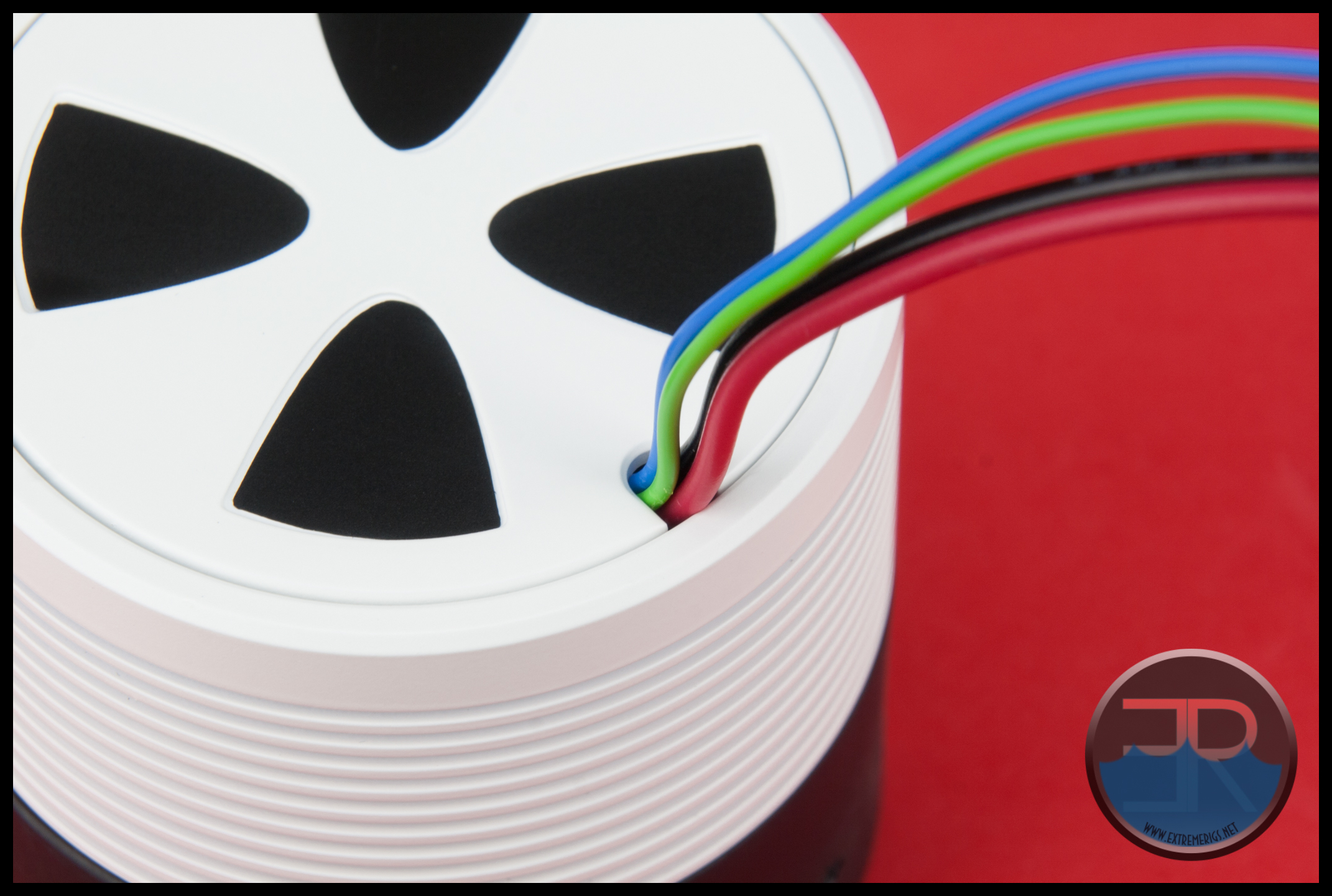
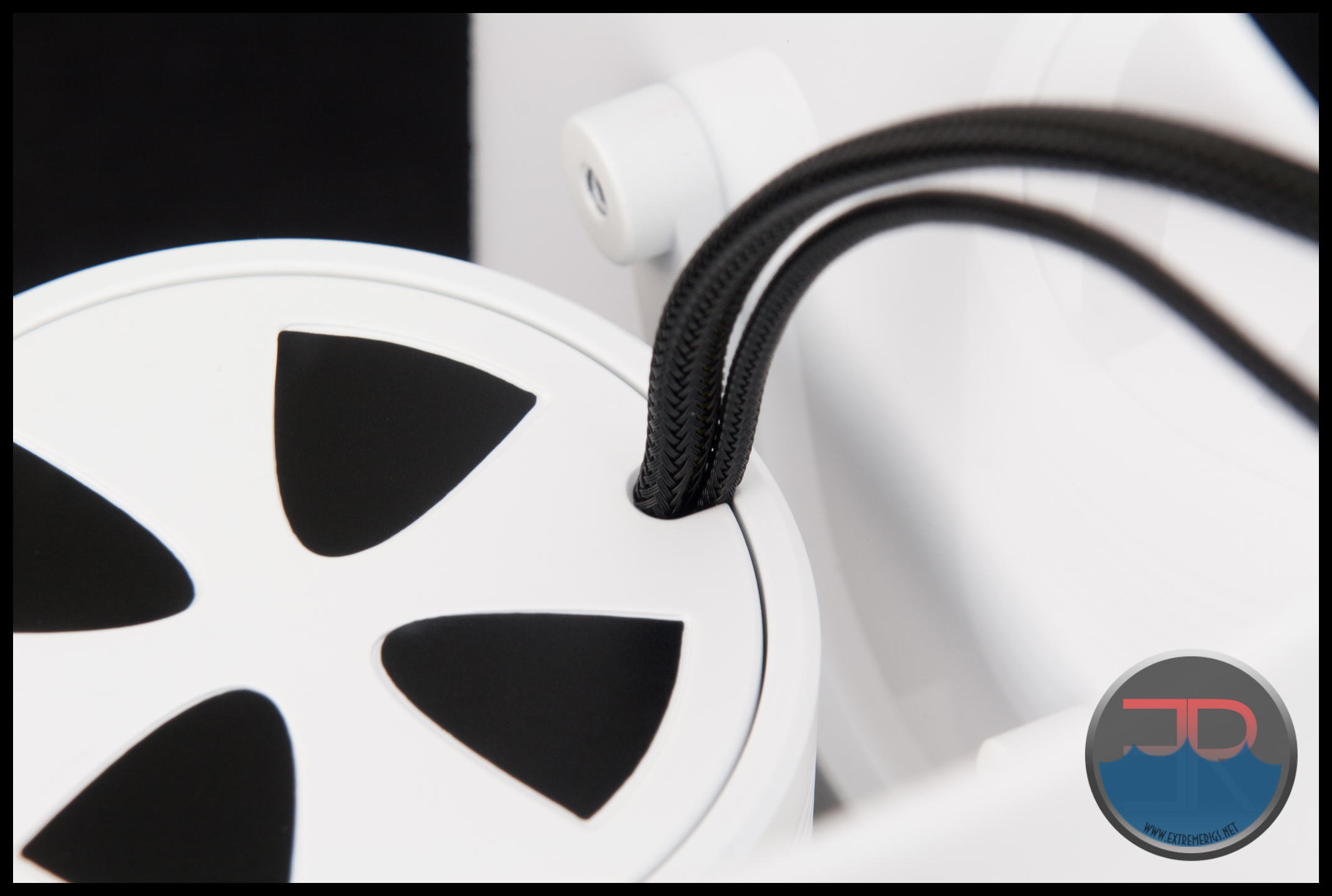
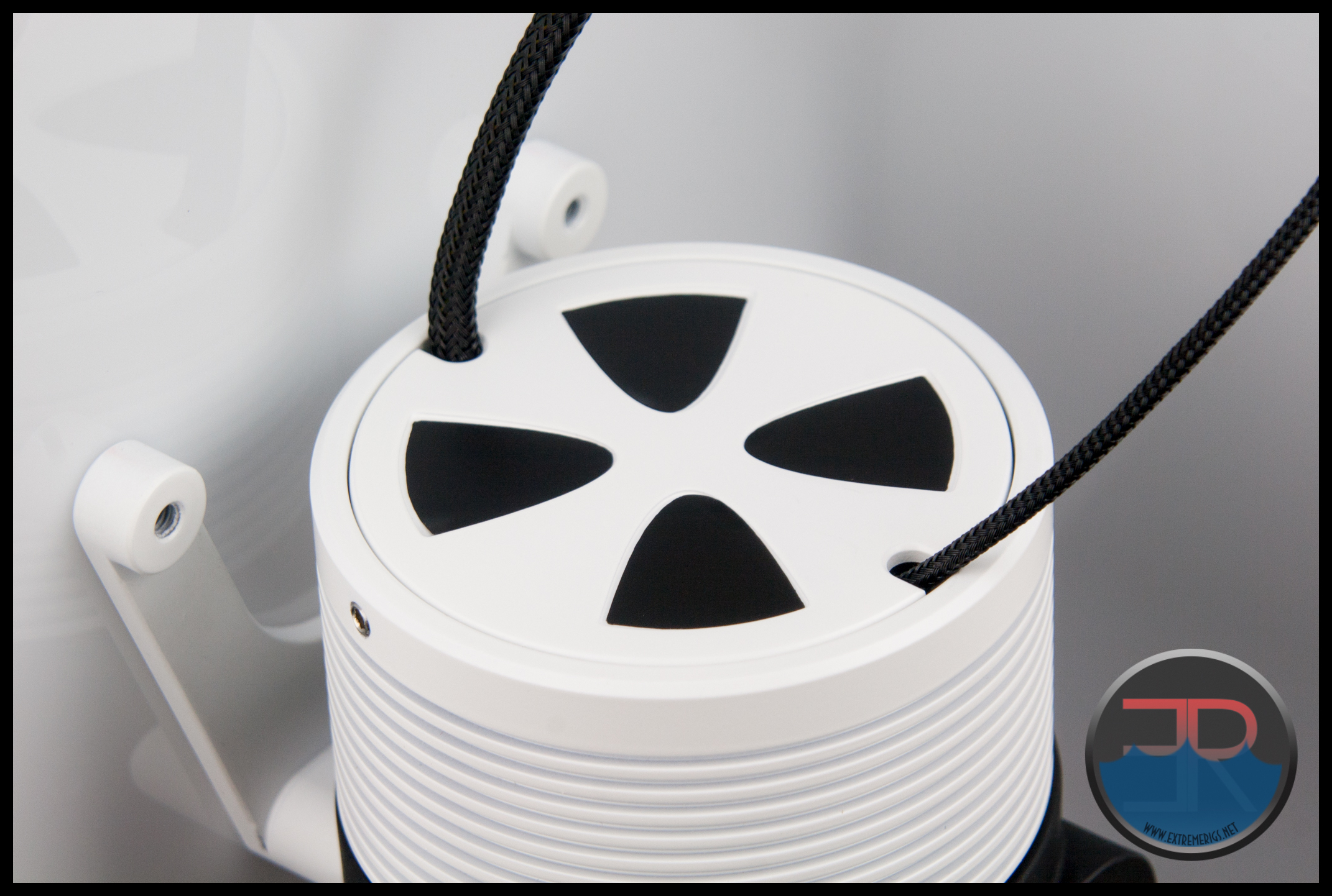
For the PWM version I believe you will have to use both cut-outs to pass the wires through the end cap such as in the following photo.
This in my opinion looks a bit ridiculous and could make the cable management look worse rather than better. If I was assembling this for a build, I would be enlarging one of the cut-outs so both sleeved wire sets came out of the same place.
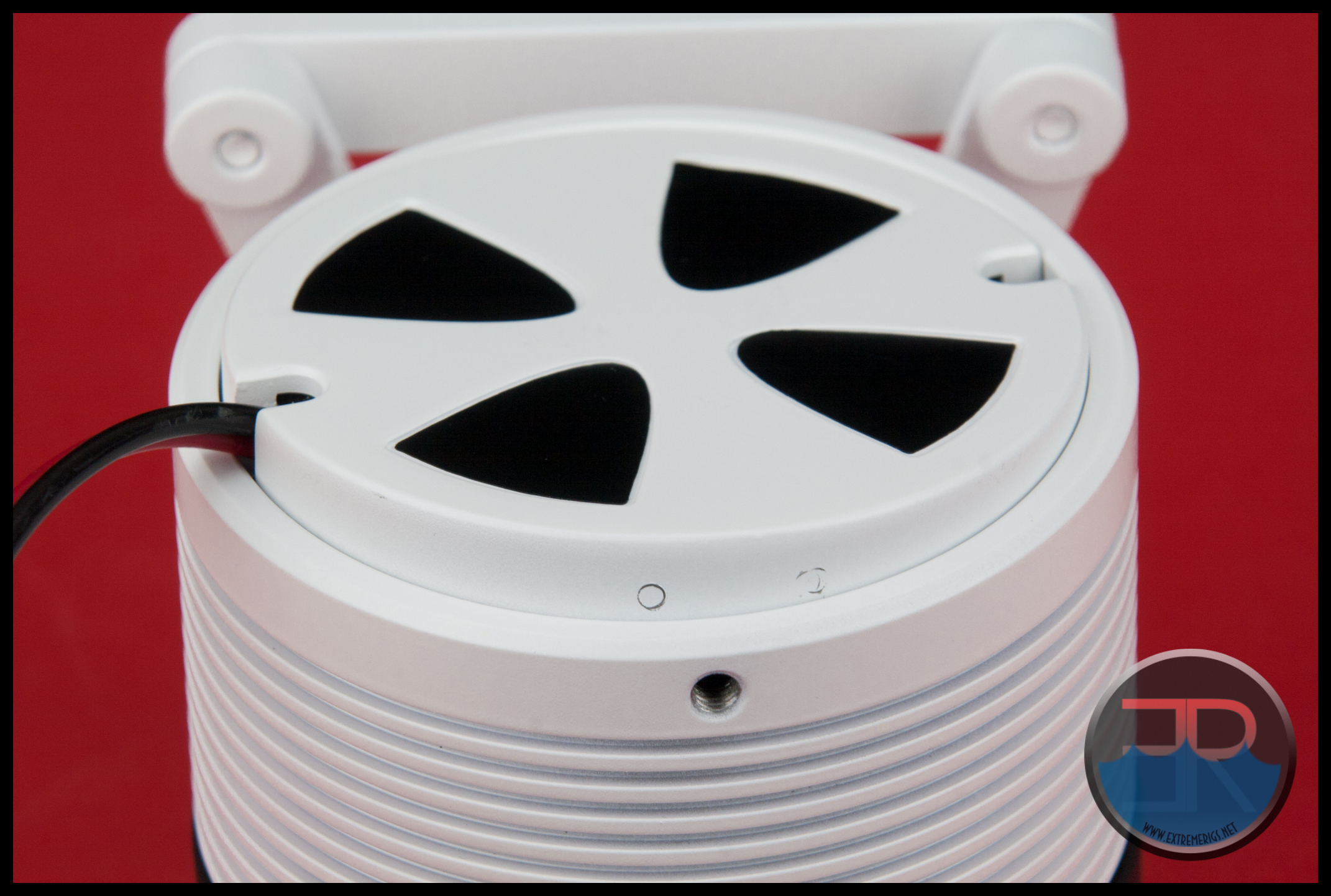
Installing a pump into the MMRS-SAP was straight forward and using the supplied template made installing the mounting bracket a sinch onto our mock chassis panel. The options the outlet port faces is limited, but at least there are options. There is no problem what-so-ever passing unsleeved pump wires through one of the cut outs on the end cap. Sleeved PWM or D5 versions with a tach wire do create a challenge though. Additionally the end cap obscures the adjustment dial on the D5 Vario, so we feel there is room for a design tweak on the end cap.
Let’s move on to see how the MMRS-SAP pump top performs.


Comments are closed.